If you’ve ever stood in a facility where temperatures run so high or sensitive that a standard thermocouple feels like it can’t keep up, chances are you’ve wondered if there’s a better way to track heat without risking damage, signal interference, or messy maintenance. For the past seven years, I’ve worked as an optical fiber supplier, talking to plant managers, process engineers, and researchers every day, and the question I get more than any other is: how do fiber-optic temperature sensors actually work? It’s easy to see why they’re growing in popularity—they don’t use electricity, they’re small enough to thread through tiny pipes, and they can monitor temperatures over miles of space without losing accuracy—but the technology behind them is often written off as too complex for anyone not in a physics lab. Today, I want to break that down, the way I do with my customers: no jargon, just real-world context, and how this matters for the work you do. Optical Fiber
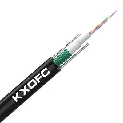
First, let’s start with what a fiber-optic temperature sensor isn’t, because that’s where a lot of confusion starts. It’s not the same as the fiber optic cables running your internet, though both use glass or silica strands that carry light. Your home internet fiber is designed to keep light from leaking out of the strand, to send data over long distances. A fiber-optic temperature sensor, by contrast, is built to intentionally interact with its surroundings, specifically the temperature, to change how that light behaves. That interaction is the core of how it works—and it’s what makes these sensors so reliable in environments where traditional sensors fail.
Let’s pull back the curtain on that silica strand first. When you shine a light into one end of a fiber, that light is made up of photons, tiny particles of light that travel through the core of the fiber (the thin center part) because the cladding, the layer surrounding the core, has a lower refractive index. Refractive index is just a fancy way of saying how much a material bends light; the core bends light enough to keep it bouncing along the inside, instead of escaping. Now, add temperature to this mix. When the surrounding temperature changes, the silica core expands or contracts, even by a tiny amount, and that changes its refractive index. But that’s only part of the story—there’s a second, even more important effect that most fiber-optic temperature sensors use, and it’s called Raman scattering.
Scattering might sound like a bad thing, but in this case, it’s exactly what we need. When photons from the light source travel along the fiber, some of them collide with the molecules of silica in the core. Most of those collisions don’t change the photon’s energy—we call that Rayleigh scattering, and it’s what makes the sky blue. But a small fraction, about one in a million photons, do change energy during the collision: either they lose energy, becoming lower-frequency (that’s Stokes Raman scattering), or they gain energy, becoming higher-frequency (anti-Stokes Raman scattering). Here’s the key: the ratio of anti-Stokes to Stokes light is almost entirely dependent on temperature. Cold surroundings mean fewer high-energy (anti-Stokes) photons, because it takes extra energy to knock an electron in silica up to a higher state, and low temperatures don’t provide that energy. Hotter surroundings mean more anti-Stokes photons, because the extra heat gives the electrons the push they need.
That’s where the magic happens. A fiber-optic temperature sensor system doesn’t just measure light—it splits the returning light after it travels the length of the fiber, separates out the Stokes and anti-Stokes wavelengths, compares their intensity, and uses that ratio to calculate the temperature at any point along the fiber. Even better, this works for distributed temperature sensing (DTS), which is what most industrial customers are using. That means a single fiber can measure temperature at every point along its entire length, up to 10 kilometers or more, with accuracy as fine as 0.5 degrees Celsius. No need to string hundreds of individual thermocouples, no wiring mess, no dead zones between sensors. For industries like oil and gas, where you need to monitor a pipeline hundreds of miles long for leak-induced temperature changes, or power plants, where reactor pipes run at 500 degrees Celsius and can’t have electrical sensors nearby for safety, this is a game-changer.
Wait, but what if someone needs just a single point measurement, not along the whole fiber? That’s where fiber Bragg gratings (FBGs) come in, another common type of fiber-optic temperature sensor that I’ve seen work brilliantly in aerospace and medical applications. A fiber Bragg grating is a small section of the fiber core where we’ve altered the refractive index in a repeating pattern, like a tiny series of mirrors spaced evenly apart. When light travels through that grating, only a very specific wavelength of light bounces back, while all others pass through. That specific wavelength is called the Bragg wavelength, and it changes when temperature changes: the glass expands or contracts, shifting the spacing between the mirrors, which shifts the wavelength that bounces back. By reading that wavelength shift, you get a precise temperature reading from exactly that grating section. The best part? You can put multiple FBGs along a single fiber, each set to respond to a different wavelength, so one fiber can monitor 10, 20, even 100 separate temperature points. That’s perfect for a wind turbine blade, where you need to track temperature at the bearing, the gearbox, and the electrical coils, all without running multiple wires.
Now, let’s talk about why this actually matters for real-world use, because I’ve seen too many customers write off fiber sensors as too niche or too expensive. Let’s compare them to the sensors you’re probably using now, thermocouples and resistance temperature detectors (RTDs). Those work great, but they have flaws: they use electricity, so they can’t be used near flammable gases or in high-electromagnetic-interference (EMI) areas like power grids. They also drift over time, needing calibration every few months, especially in harsh environments. And if one thermocouple breaks, you might lose a whole section of data, or have to replace dozens at a time. Fiber-optic sensors? No electricity running through the sensing part, so they’re intrinsically safe for Class 1 Div 1 areas, where even a tiny spark from a broken wire could cause an explosion. They don’t get affected by EMI, so they work right next to a 10,000-volt motor without noise in the data. And because they’re made of silica, they can handle temperatures from as low as -200 degrees Celsius (way colder than liquid nitrogen) up to 1,800 degrees Celsius, which is way beyond what any metal thermocouple can manage.
I mentioned calibration, too—for my customers who use DTS, I tell them that fiber sensors rarely need calibration, because the Raman ratio is a physical constant of silica that we can rely on, not a metal wire that wears out. Of course, like any technology, there are limits. For very high-precision point measurements, FBGs might be more expensive than a simple RTD, and DTS doesn’t have the same spatial resolution as a grid of small thermocouples, though it’s getting better every year. The biggest hurdle I see is that a lot of people don’t know these sensors exist, or think they’re only for lab use. That’s why I spend time walking new customers through how to integrate them into their existing systems, not just selling them a spool of fiber and a reader.
Let’s use an example that’s super common for my business: a chemical plant I worked with last year, making specialty polymers. They had a batch reactor that ran at 120 degrees Celsius, but the reaction sometimes had hotspots that would ruin the batch if they hit 150 degrees. They were using 18 thermocouples around the reactor, but they kept missing hotspots that formed between the sensors, because the thermocouples could only measure temperature at their exact locations. When we installed a single 5-meter fiber FBG sensor with 12 FBG points spaced 40 centimeters apart, they immediately caught a hotspot that had been forming for three hours between two original thermocouples. It cut their batch failure rate by 70% in the first quarter, and they haven’t had to calibrate the sensors once in the year since. That’s the impact this technology can have.
Another example: a wind farm in the Midwest that was monitoring their 100-foot turbine blades for ice formation and overheating bearings. They tried thermocouples, but the EMI from the turbine’s generator made the temperature data unreadable. We installed a single DTS fiber along the length of each blade, and now they get real-time temperature data every 2 centimeters along the blade. That lets them trigger ice protection systems before ice causes damage, and catch overheating bearings before they fail, saving them millions in downtime and repair costs. For this customer, switching to fiber sensors was actually cheaper than replacing all the thermocouples and running new shielded wiring, because one fiber does the work of dozens of sensors.
Now, if you’re reading this, you might be thinking: “Okay, that sounds great, but how do I actually use this for my operation?” The first step is figuring out which type of fiber sensor fits your needs. If you need to measure temperature over a long, continuous stretch, like a pipeline or a tunnel, DTS is the way to go. If you need multiple precise point measurements, FBGs are better. And if you have a harsh environment with flammable materials or high EMI, fiber sensors are often the only safe option. I always tell customers to ask three questions: How long do I need to monitor? How precise does my temperature measurement need to be? And do I need multiple points or a full continuous profile?
As someone who’s been in the optical fiber supply business for years, I’ve seen firsthand how this technology has evolved from a lab curiosity to a workhorse for industrial, energy, aerospace, and even medical applications. The key takeaway here isn’t that fiber sensors are better than every other sensor for every job, but that they fill a gap that traditional sensors can’t. They’re reliable, they’re safe, they save money on maintenance and calibration, and they provide data that you just can’t get any other way.
If you’re tired of missing hotspots, dealing with wiring headaches, or wasting money on constant calibrations that don’t give you the full picture, I’d love to talk through how a fiber-optic temperature sensor could work for your operation. I’ve helped hundreds of customers pick the right solution, walk through installation, and make sure they get accurate, consistent data without the hassle. Don’t let the technology feel intimidating—sometimes the best way to solve a problem is with a sensor that works with your environment, not against it.
Optical Fiber References
- B. Culshaw, Optical Fiber Sensors for Structural and Industrial Monitoring, Artech House, 2006.
- J. W. Miller, Distributed Fiber Optic Temperature Sensing: Principles and Applications, SPIE Press, 2012.
- A. Othonos, Fiber Bragg Gratings: Fundamentals and Applications, Artech House, 1999.
- Federal Energy Regulatory Commission, “Applications of Fiber Optic Sensors in the Electric Power Industry”, 2018.
- ASTM International, “Standard Guide for Distributed Fiber Optic Temperature Sensing (DTS) for Industrial Applications”, ASTM E2658-16, 2016.
Hangzhou Lin’an Kexin Optical Cable Co., Ltd.
As one of the most professional optical fiber manufacturers and suppliers in China, we’re featured by quality products and good price. Please rest assured to wholesale discount optical fiber made in China here and get pricelist from our factory. Customized orders are welcome.
Address: No. 28 Linglong Street,Lin’an Area, Hangzhou City, Zhejiang Province, China
E-mail: sales@kexincable.com
WebSite: https://www.kexincable.com/
